Part 2 of 7 in the Hardware hacking series. Part 1: updating the firmware on a Pinecil V2.
Nothing on my bench is expensive. I bought it one problem at a time, and that matters for this series. The point is not to show off lab gear, it is to show how little it takes to look inside a device, which is also how little an attacker needs. If a cheap logic analyzer and a serial cable can show what a router prints at boot, then “nobody will ever open it” is not a security control.
The rules before the tools
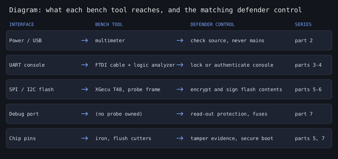
The diagram above is one I drew to map each interface a device exposes to the bench tool that reaches it and the control that closes it.
Everything here happens on hardware I own and am allowed to take apart. No work devices, no borrowed ones, nothing that belongs to a neighbour or a client.
I do not open, probe or connect anything that is plugged into mains. Many small devices, such as smart plugs, bulbs and some power bricks, have supplies that are not isolated from mains, so a board’s ground can sit at mains potential. I work on boards powered from a proper low-voltage adapter, a battery or USB, and if I am unsure what powers a board, I do not connect anything.
Then the boring habits. Power down and unplug before soldering, swapping a chip or moving a probe onto a chip. For UART and logic captures I make the connections with the target off and power it up afterwards, from its own supply only, never from the serial cable as well. Ground goes on first and comes off last. I touch an earthed metal object, such as an unpowered PC case, before handling a board, and I hold boards by the edges, because static discharge can damage chips without any visible sign. If you use a wrist strap, use one with a built-in series resistor and never wear it near anything that could be connected to mains. Wear safety glasses when cutting leads or soldering, and keep some ventilation going.
The iron: Pinecil V2
I covered the firmware in part 1. It is a small USB-C powered iron running IronOS, and I use it for tinning wires, pin headers and joint rework. A hot tip burns skin and scorches a desk, so it sits in its stand while it is on, and I let it cool before putting it away.
The logic analyzer: HiLetgo 24 MHz, 8 channels
This is a cheap Saleae-style clone that works with the open source sigrok and PulseView software through the fx2lafw driver. It records when each of up to eight digital lines goes high or low. It does not measure voltage and it does not replace a multimeter. It gives you timing.
Two things matter in practice. The sample rate tops out at 24 MHz, but a UART at 115200 baud has bits about 8.68 microseconds long, so at 24 MHz you get roughly 208 samples per bit, far more than needed. The other is voltage. I have not found a datasheet for mine, so I treat its inputs as unprotected with a threshold I cannot adjust. I measure the target’s logic level with a multimeter first, with the target powered from its own supply and nothing else connected, I connect the analyzer’s ground before any signal lead, and I do not expect it to read a 1.8 V signal reliably.
In part 6 I decode I2C and SPI with it. Here is PulseView with a capture loaded. This is a synthetic signal I generated with a Python script (8N1 at 115200 baud, written as a raw binary file and opened in PulseView), not a capture from a device.

The image shows PulseView with a synthetic UART trace on channel 0 and a time scale in milliseconds along the top.
The serial cable: FTDI FT232RL, 5 V
A USB-to-serial cable with an FTDI chip and a 6-pin 0.1 inch female header. It lets a PC talk to the UART console that many routers and embedded boards expose on a few unpopulated pads. A UART needs a transmit line, a receive line and a ground. The line idles high, and each byte is framed by a low start bit and a high stop bit. There is no clock, so both sides have to agree on the baud rate in advance.
Mine is sold as a 5 V cable, and I expect its data lines to be 5 V too, not only the red power wire. I will confirm that by measuring the idle level of its TX line with the USB end plugged in. Many boards run their UART at 3.3 V, and a 5 V transmit line into a 3.3 V receiver is the real risk, which leaving the red wire unconnected does not fix. I never connect the cable’s 5 V wire to a target, I connect only ground, TX and RX (cable TX to target RX, target TX to cable RX), and I measure the target’s logic level first. Part 3 makes this cable safe on 3.3 V targets, with the numbers worked out.
The programmer: XGecu T48
A universal programmer with a ZIF socket and a set of adapters (mine came with 19) for SPI and I2C EEPROM, NOR and NAND flash, microcontrollers and BIOS chips. Its software, Xgpro, is Windows only, so I won’t show screenshots of it here and I only download it from the vendor. Chips go in the socket after I have taken them off the board, which means desoldering, heat and a steady hand. Orientation and supply voltage have to be right before I start a read, because a chip in backwards or at the wrong voltage can be destroyed.
The probe frame
A small frame with four probe pens that holds against a board and touches the pads or pins of a chip without desoldering it. It is sold as a BDM frame, though it is just a probe holder and has nothing to do with Motorola’s debug interface. I use it when I can’t or won’t desolder something, and it is where most of my failed reads come from. The rest of the board is still attached to the chip, so other devices on the same bus can interfere. Back-powering can also damage the board or the programmer, so for in-circuit reads the board stays unpowered except for whatever the programmer supplies, at the voltage the chip expects. Part 5 covers reading in circuit, and why I read every chip twice and compare hashes before I trust a dump.
The small stuff
DOWELL micro flush cutters for trimming leads, always cutting away from my face because clipped leads fly. A pack of 120 Dupont jumper wires for temporary connections. A sheet of PTM7950 phase-change thermal pad for putting a device with a heatsink back together properly. A pad that has been removed gets replaced rather than reused, and old residue is cleaned off with isopropyl alcohol first.
What is not on the bench
No JTAG or SWD probe. Part 7 on debug ports is therefore about concepts, pinouts and how vendors lock those ports, not a walkthrough on my own hardware.
Why a defender should care
Every tool above is cheap and easy to buy, which is the whole argument. If your product ships with an open UART console, an unprotected SPI flash holding secrets in plain text, or a debug port that never got locked, assume someone with this bench will find it. The fixes are in the design: authenticate or close the console, encrypt and sign what is in flash, and fuse the debug port before shipping. The next parts show each one from the owner’s side of the soldering iron.
Other parts of the Hardware hacking series: 1, updating the firmware on a Pinecil V2; 2, the bench I work on; 3, using my 5 V FTDI cable on 3.3 V UARTs; 4, finding the UART console on a router I own (publishes Nov 10); 5, reading SPI flash without wrecking it (publishes Nov 11); 6, decoding I2C and SPI with sigrok (publishes Nov 12); 7, JTAG and SWD basics (publishes Nov 13).