Part 6 of 7 in the Hardware hacking series. Part 1: updating the firmware on a Pinecil V2. Part 2: the bench I work on. Part 3: using my 5V FTDI cable on 3.3V UARTs. Part 4: finding the UART console on a router I own. Part 5: reading SPI flash without wrecking it.
Much of the interesting traffic inside a device never touches a network. A sensor talks to a microcontroller over I2C, a microcontroller talks to its flash over SPI, and a security chip hands out keys over one or the other. A logic analyzer is the cheapest way to listen. Mine is the HiLetgo 24 MHz, 8-channel clone that works with sigrok and PulseView through the fx2lafw firmware.
Everything here is for boards I own. I only clip onto boards that run from a low-voltage adapter or a battery, never anything with mains-voltage circuitry (a low-voltage output from a mains supply doesn’t make the board safe to touch while it is plugged in), and never while it is plugged into the wall. The analyzer is input only. I never connect any adapter, programmer or other output to a bus the board is already driving. I touch an earthed metal object before handling a board (a wrist strap is better), I move leads only with the board powered down, and I connect the analyzer’s ground first. Small clips can short neighbouring pins, so I check them before powering up. I measure the bus voltage with a multimeter on the powered low-voltage board before attaching any signal lead, and I only clip onto a line if that level is within what my analyzer is rated for. I haven’t verified that rating for my clone, so I treat anything above 3.3V as off limits. Plenty of hobby boards still run at 5V.
The captures below are synthetic. I generated the signals with a short Python script and decoded them with sigrok-cli 0.7.2 in a throwaway container, so I control exactly what is on the wire. They are not recordings of real hardware.
What the analyzer does and doesn’t do
It samples eight inputs at a fixed rate and records high or low for each. Everything else, the bytes and addresses and ACK bits, is the decoder reconstructing meaning afterwards. When the decode is garbage the tool won’t say so. It prints confident nonsense, which makes sample rate and decoder options the whole game.
I2C: two wires, open drain
I2C uses a clock line (SCL) and a data line (SDA). Devices only pull the lines low. Pull-up resistors bring them back high, which is why the spec says the output stages must be open-drain or open-collector (NXP UM10204 rev 7, section 3.1.1). Standard-mode runs up to 100 kHz, Fast-mode to 400 kHz and Fast-mode Plus to 1 MHz (Table 11). The maximum input low level (VIL) is 0.3 x VDD and the minimum input high level (VIH) is 0.7 x VDD (Table 10), which on a 3.3V bus is 0.99V and 2.31V. They are limits a device has to meet, not a single switching point.
The pull-ups matter for what you see, not just whether the bus works. The line rises with an RC curve, and the spec caps the rise time at 1000 ns in Standard-mode, 300 ns in Fast-mode and 120 ns in Fast-mode Plus (Table 11). The time to go from 30% to 70% of VDD is 0.8473 x R x C (section 7.1). A 10 kohm pull-up on 50 pF of wiring and probe capacitance gives about 424 ns: fine for a 100 kHz bus, too slow for a 400 kHz one. The 50 pF is my assumption for the example, not a measurement. Slow edges like that break the spec, and no decoder setting will fix them.
Here is a decode of a synthetic 100 kHz transaction, the kind of thing a 24C02-style EEPROM does: write a memory address of 0x00 to device 0x50, restart, read four bytes. The generator sampled at 2 MHz, so 20 samples per bit.
$ sigrok-cli -I binary:numchannels=8:samplerate=2000000 -i i2c_100k.bin \
    -P i2c:scl=0:sda=1 \
    -A i2c=address-write:address-read:data-write:data-read:nack
i2c-1: Write
i2c-1: Address write: 50
i2c-1: Data write: 00
i2c-1: Read
i2c-1: Address read: 50
i2c-1: Data read: 41
i2c-1: Data read: 42
i2c-1: Data read: 43
i2c-1: Data read: 44
i2c-1: NACK
The 0x50 is the 7-bit address. On the wire it is the byte 0xA0 for a write and 0xA1 for a read, because the lowest bit is the direction, and tools disagree on which form they show. The trailing NACK is correct: a controller NACKs the last byte it reads to tell the device to stop sending.
Sample rate: the setting that quietly ruins everything
Now the same synthetic signal, decimated so it was sampled at 200 kHz. That is two samples per bit. The decoder still runs.
$ sigrok-cli -I binary:numchannels=8:samplerate=200000 -i i2c_100k_at200k.bin \
    -P i2c:scl=0:sda=1 \
    -A i2c=address-write:address-read:data-write:data-read:nack
i2c-1: Write
i2c-1: Address write: 50
i2c-1: Data write: 00
i2c-1: Data write: 50
i2c-1: NACK
i2c-1: Data write: 20
i2c-1: NACK
i2c-1: Data write: 21
i2c-1: Data write: 21
i2c-1: NACK
i2c-1: Data write: 22
The first two bytes survive by luck. After that it invents data bytes and NACKs that never happened, and it never reports the read at all. Nothing in the output says the sample rate was too low.
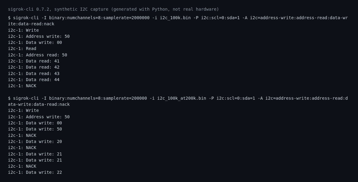
Terminal output I captured from sigrok-cli 0.7.2 decoding my synthetic I2C signal: the correct 2 MHz decode first, then the same signal sampled at only 200 kHz producing invented bytes and NACKs.
My rule of thumb, and it is a rule of thumb rather than anything from a standard, is at least four samples per bit and ten if I can afford it. With a 24 MHz maximum that gives me:
- 100 kHz I2C: 240 samples per bit at 24 MS/s, so there is plenty of room.
- 400 kHz I2C: 60 samples per bit at 24 MS/s, still comfortable.
- 1 MHz I2C: 24 samples per bit.
- SPI at 8 MHz: 3 samples per clock period, which is already below my four-sample minimum.
- SPI at 24 MHz: 1 sample per clock period. Useless.
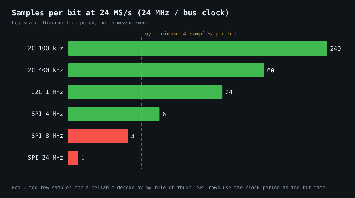
Bar chart I drew (not a measurement): samples per bit at 24 MS/s for I2C at 100 kHz, 400 kHz and 1 MHz and SPI at 4, 8 and 24 MHz, with my four-sample minimum as a dashed line.
A lot of SPI flash runs well above 8 MHz, so this analyzer cannot capture a full-speed flash read at all. For a part like that I either slow the controller down, if the firmware lets me, or I accept that I will only see the command phase of a slow operation. Higher rates also mean more data: 24 MS/s on eight channels is roughly 24 MB per second, so half a minute is hundreds of megabytes. I keep the rate as low as the bus allows.
SPI: four wires and a mode you have to guess
SPI has a clock, MOSI, MISO and a chip select, but no formal addressing and no ACK. The decoder needs to know the clock polarity (CPOL) and phase (CPHA): which level the clock idles at, and whether data is sampled on the first or second edge. Get it wrong and the bytes come out shifted, not obviously broken.
Here is a synthetic 500 kHz SPI mode 0 read: command 0x03, a 24-bit address of 0x000100, then four data bytes. I put the bytes 7F 45 4C 46 on MISO, the start of an ELF header, because that is what a lot of firmware starts with. First the correct mode, looking at each data line separately:
$ sigrok-cli -I binary:numchannels=8:samplerate=2000000 -i spi_500k.bin \
    -P spi:clk=0:mosi=1:miso=2:cs=3:cpol=0:cpha=0 -A spi=mosi-data | sed 's/spi-1: //' | paste -sd' '
03 00 01 00 00 00 00 00

$ ... -A spi=miso-data | sed 's/spi-1: //' | paste -sd' '
00 00 00 00 7F 45 4C 46
The four zero bytes on MISO are the chip not driving anything meaningful while it receives the command and address, and the last four are the payload. Now the same file decoded with CPHA=1:
$ ... cpol=0:cpha=1 -A spi=miso-data | sed 's/spi-1: //' | paste -sd' '
00 00 00 00 FE 8A 98 8C
7F 45 4C 46 has become FE 8A 98 8C, which is the same bits shifted left by one position. If you are expecting a magic number and don’t see it, try the other mode before you conclude the data is encrypted. The Winbond W25Q128JV I read in part 5 supports modes 0 and 3 (datasheet revision F), so for that chip those are the two I try first.
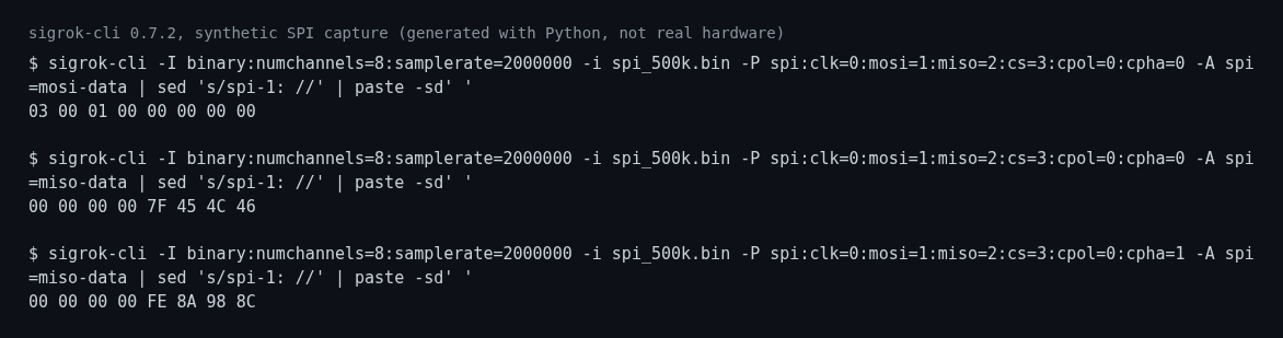
Terminal output I captured from sigrok-cli 0.7.2 decoding my synthetic SPI signal: MOSI and MISO in the right mode, then MISO with CPHA wrong, where 7F 45 4C 46 comes out as FE 8A 98 8C.
What I check before I trust a decode
I look for a known value: a magic number, a device ID, a repeated command. If I can’t find one, I don’t believe the decode. I also decode the same capture at two sample rates and check that chip select frames the transactions the way I expect. It’s the same discipline as reading a flash chip twice and comparing hashes.
Next is part 7, on JTAG and SWD, the debug ports that vendors are supposed to lock before a product ships.
Other parts of the Hardware hacking series: 1, updating the firmware on a Pinecil V2; 2, the bench I work on; 3, using my 5V FTDI cable on 3.3V UARTs; 4, finding the UART console on a router I own; 5, reading SPI flash without wrecking it; 6, decoding I2C and SPI with sigrok; 7, JTAG and SWD basics.